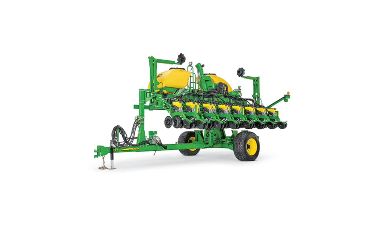
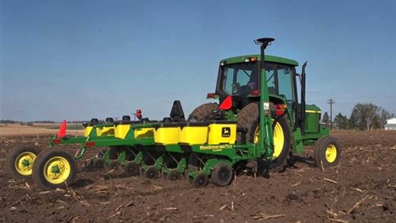
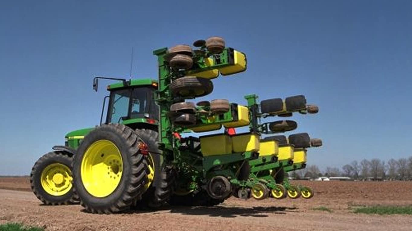
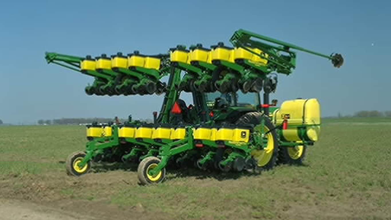
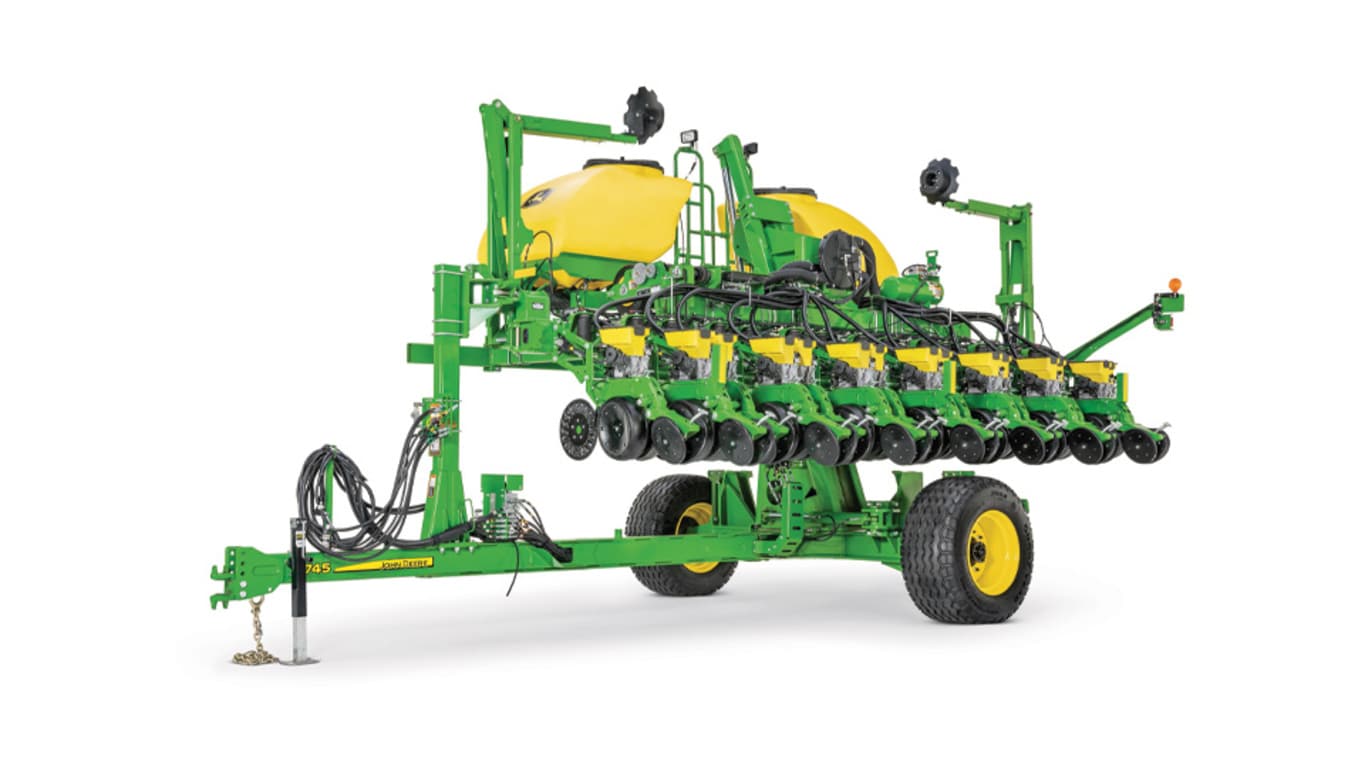
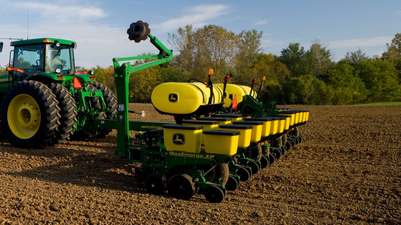
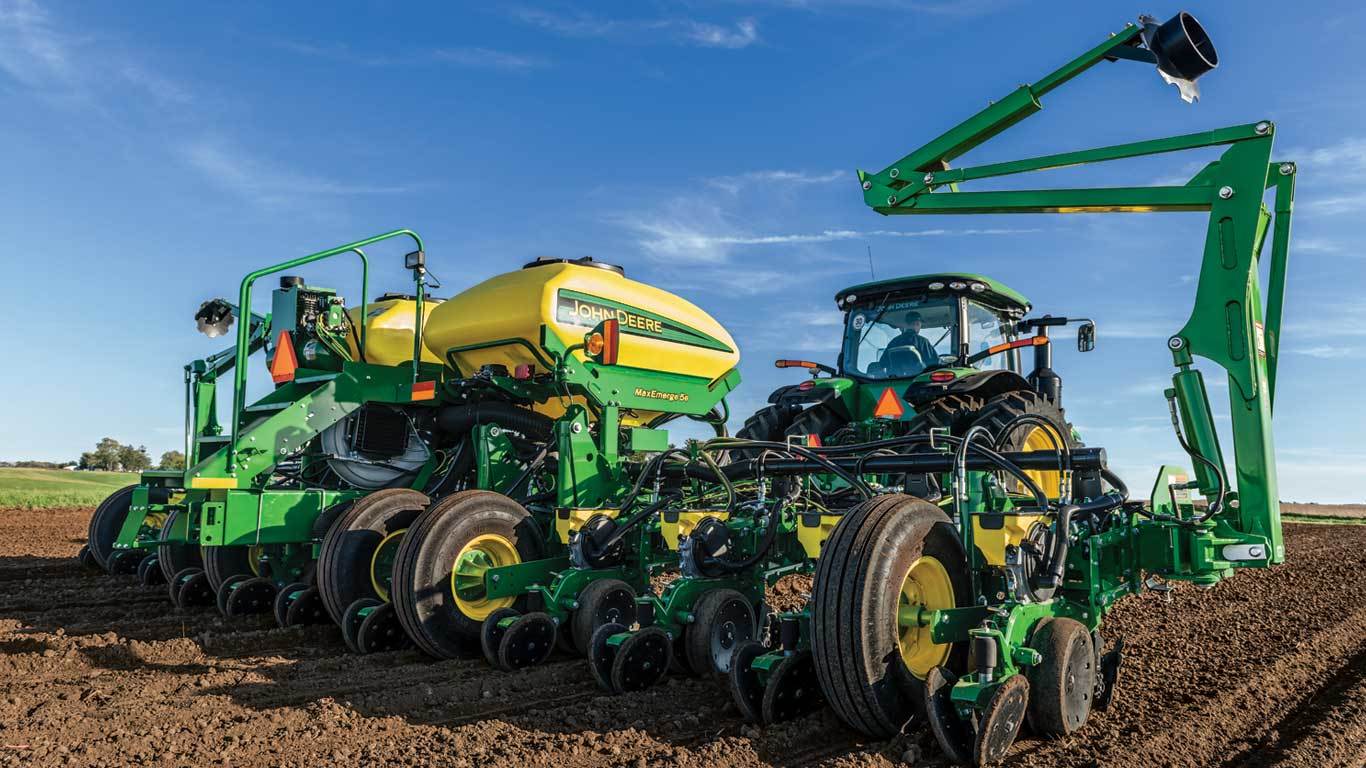
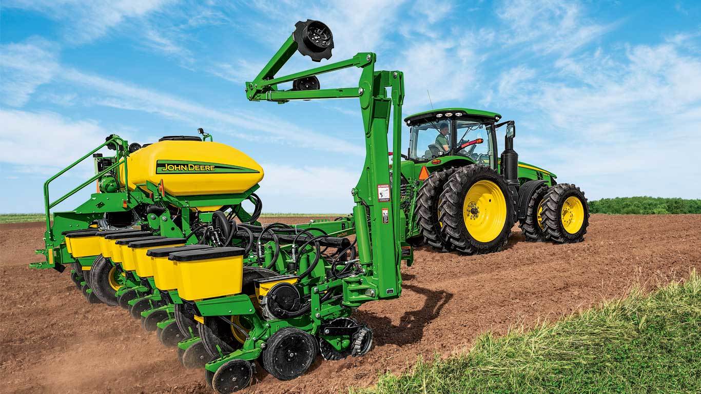
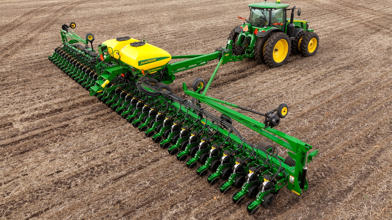
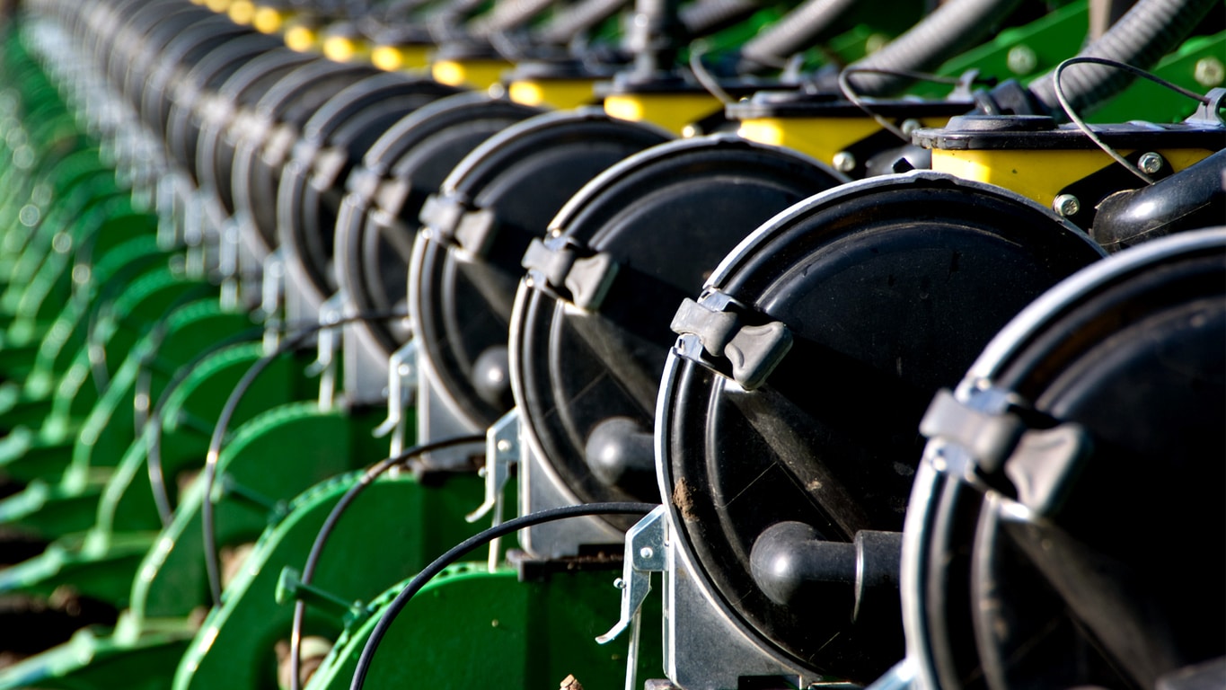
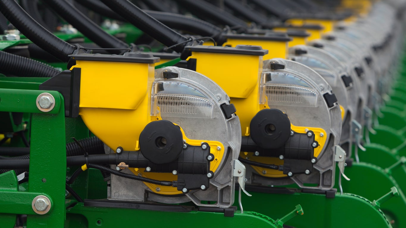
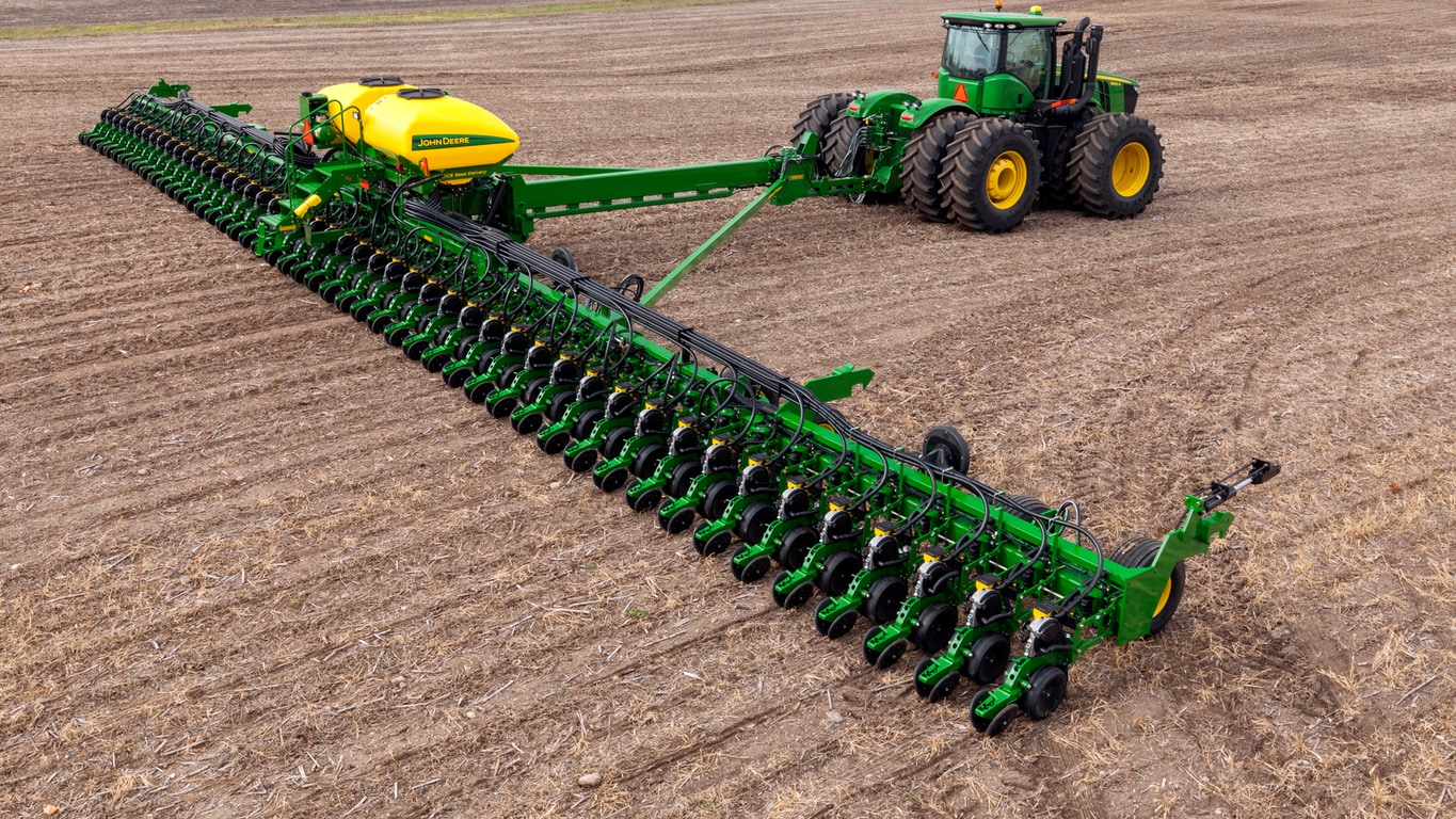
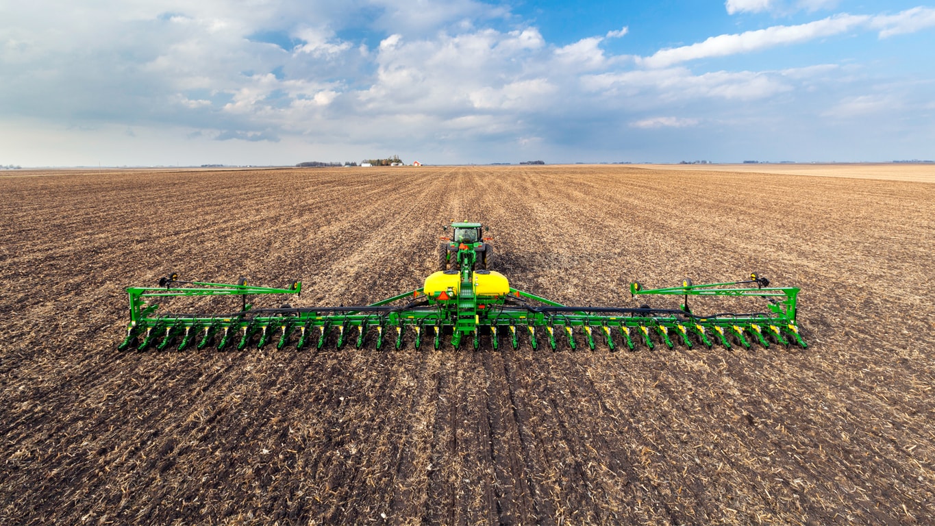
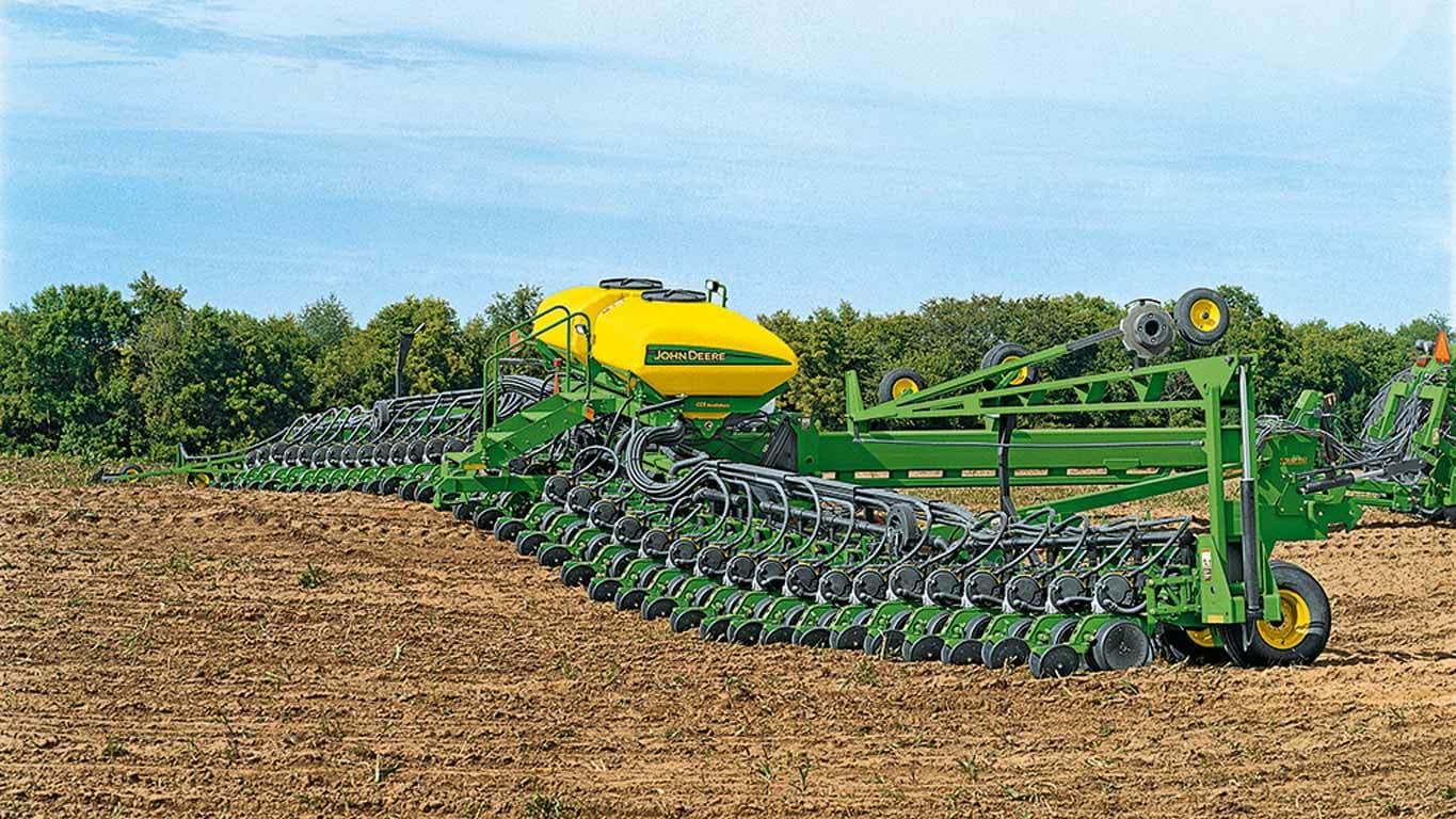
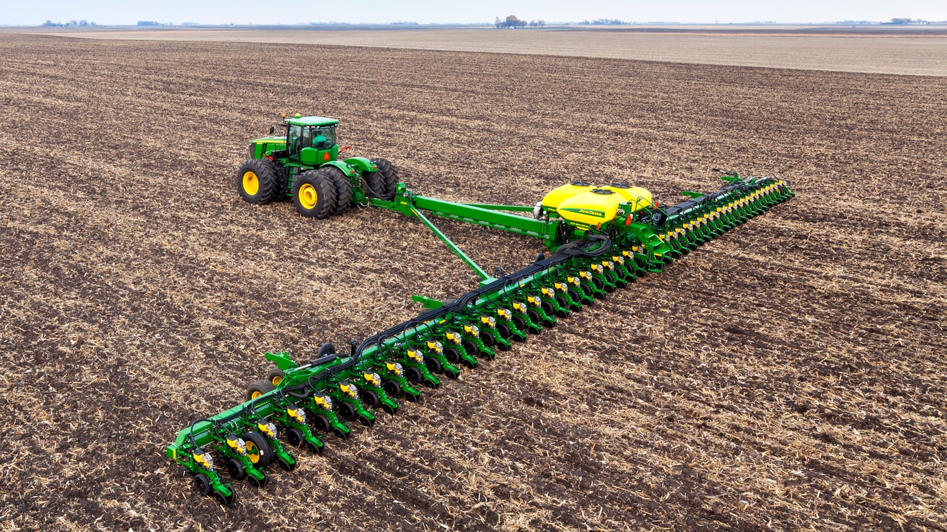
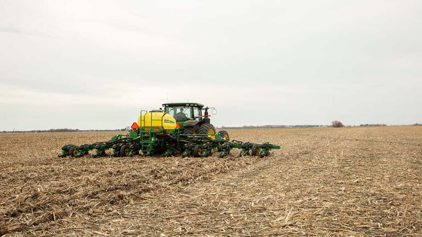
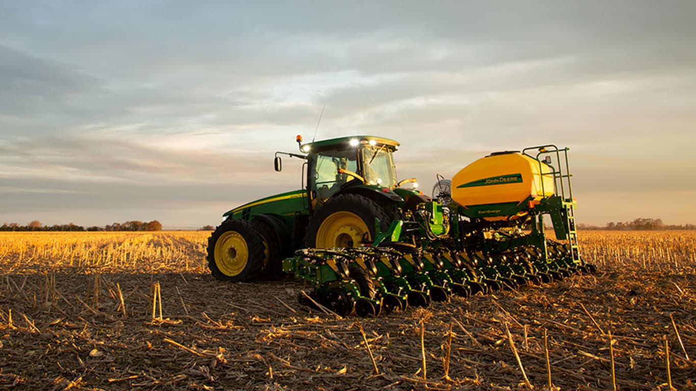
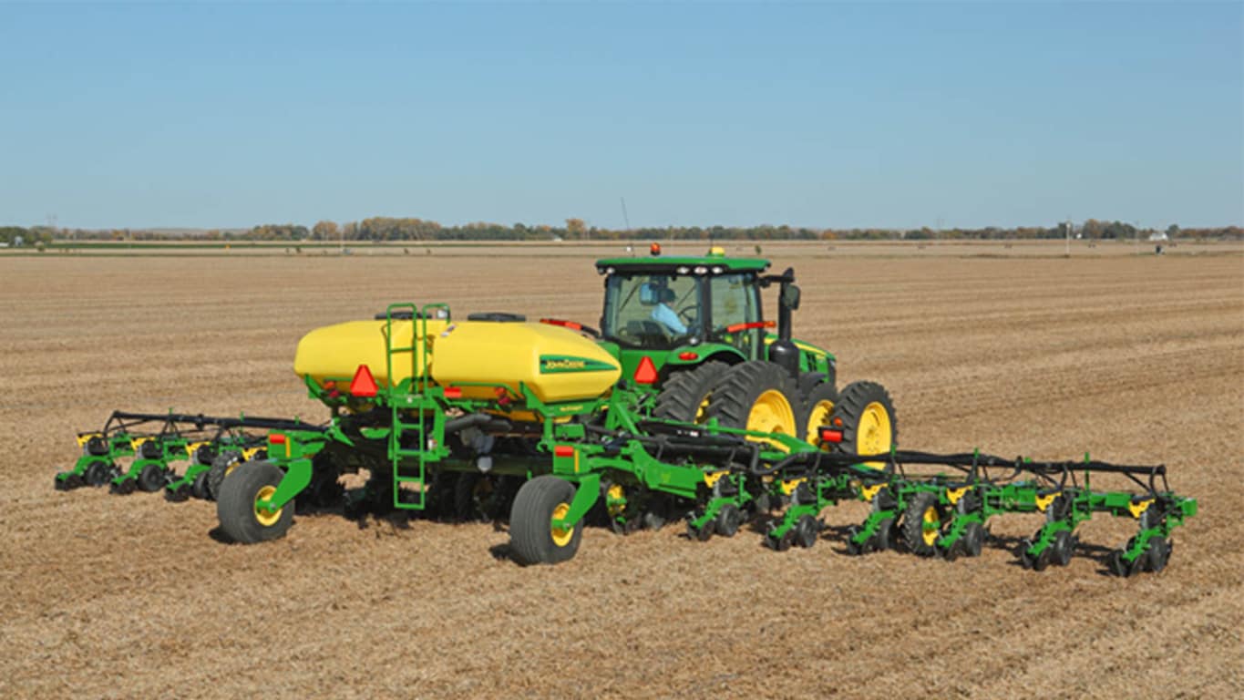
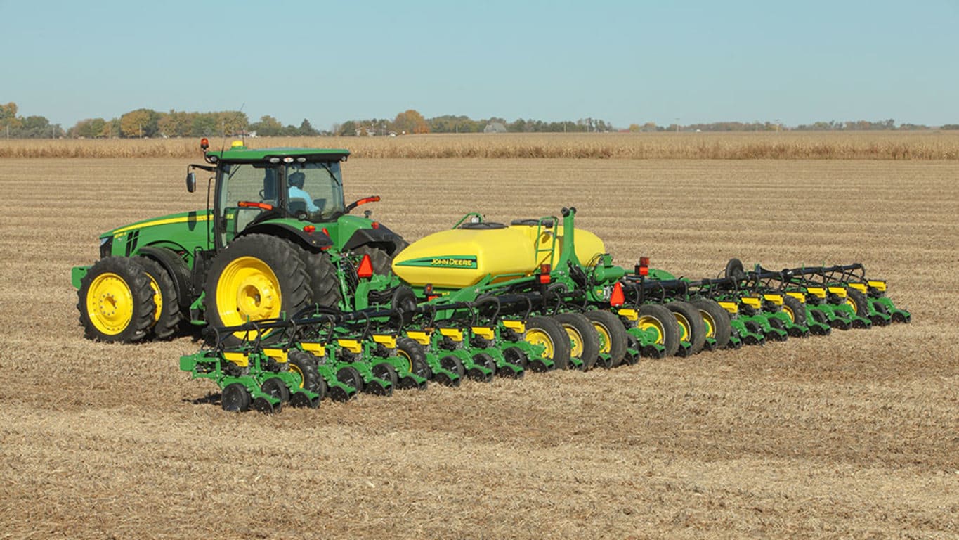
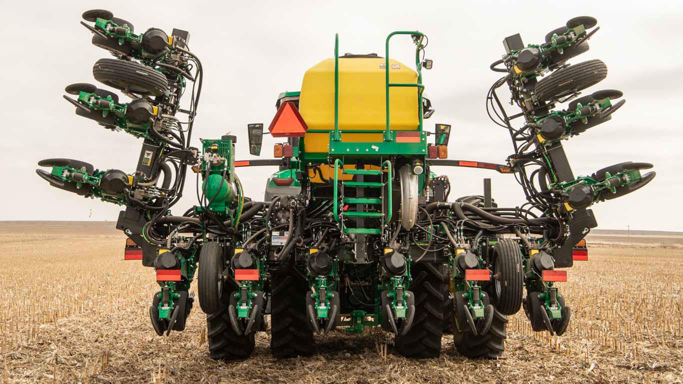
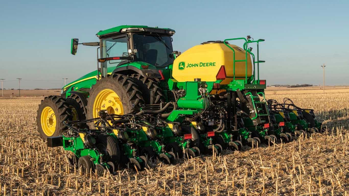
 Pneumatic downforce on 1745 Planter
Overview
Planter row-unit downforce is an important factor to ensure consistent and proper depth control. With too little downforce, planter gauge wheels can lose ground contact and seeds will be planted at a shallow depth. This can result in uneven emergence, which studies have shown can impact yield 5 to 9 percent1. With too much downforce, furrow sidewalls can become smeared and compacted. Compacted sidewalls can result in hatchet roots, where plant roots grow parallel with the furrow but do not branch out between the rows.
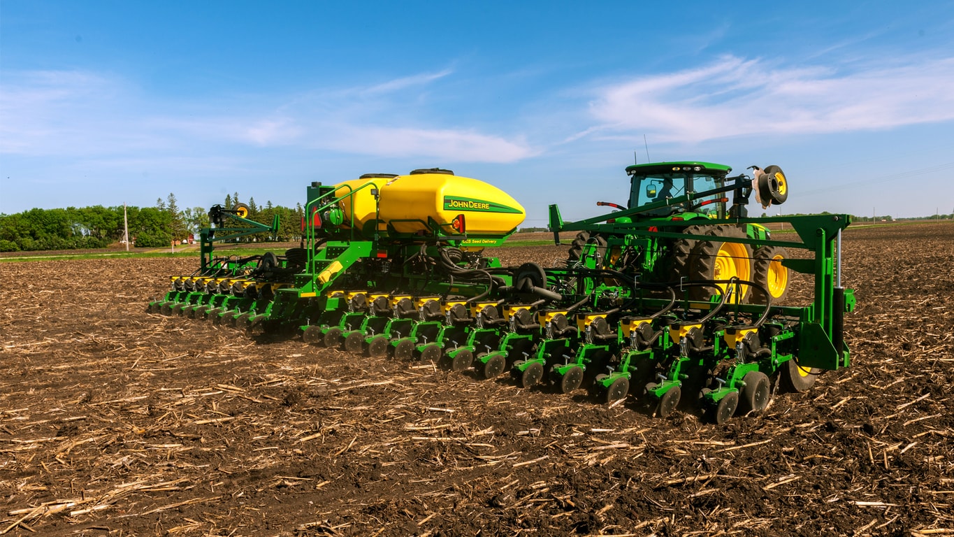
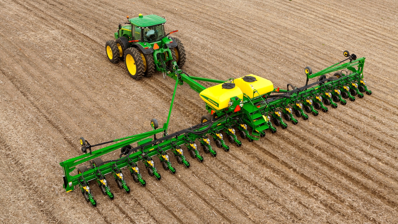
Depending on the level of control the producer is looking for, the 1745 Planter offers three levels of downforce.
Benefits
- Adjustable heavy-duty downforce springs provide four settings to match downforce requirements to field conditions: 0 kg (0 lb), 56.7 kg (125 lb), 113.4 kg (250 lb), and 181.4 kg (400 lb). Downforce is manually adjustable row-by-row.
- Manual control of pneumatic downforce provides simple adjustment of the whole planter from the electric compressor mounted on the front mast of the planter. The amount of downforce applied is infinitely adjustable from 6.8 to 181.4 kg (15 to 400 lb). Pneumatic downforce provides more consistent downforce throughout the range of row-unit travel compared to heavy duty downforce springs.
- Integrated control of pneumatic downforce provides simple adjustment of the whole planter conveniently from the tractor cab with the SeedStar™ XP monitoring system. Operators can see gauge wheel margin readings on three rows of the planter and either add or remove air from the pneumatic system to maintain a good level of load (margin) on the gauge wheels. The amount of downforce is infinitely adjustable from 6.8 to 181.4 kg (15 to 400 lb).
Adjustable heavy-duty downforce springs
 Adjustable heavy-duty downforce springs on 1745 Planter
- Four downforce settings are manually adjusted for each row-unit.
- Rows behind tires can be set on a heavier setting.
- Downforce adjustments will take more time compared to pneumatic downforce systems.
Pneumatic downforce system - Manual
 Electric compressor and gauge on 1745 Planter
- Fill all the pneumatic air bags from one location on the planter.
- It includes simple on/off operation.
- The system has a valve stem which allows filling with shop air for faster fill times or for use as a backup if the compressor stops working.
- Split rows are plumbed on a separate circuit. This allows the air to be released only on the split rows when they need to be locked up for planting on 76.1-cm (30-in.) spacing. Set-point pressure is controlled for all rows when all rows are planting.
Pneumatic downforce system – Integrated
 Integrated compressor tank on 1745 Planter
 SeedStar XP downforce margin page
Using set point pneumatic downforce
Watch the following video to better understand setting downforce by manually adjusting the pressure in the air bags.
SeedStar XP Operation and Adjustment – Using Set Point Pneumatic Downforce
1Doerge, T., Jeschke, M., and Carter, P. Planting outcome effects on corn yield. Crop Insights, Vol. 25, No. 1. DuPont Pioneer. https://johndeere.widen.net/s/5gzsdtffkv/planting-outcome-effects-on-corn-yield
 SeedStar XP ride quality page
- Integrated downforce comes with an electric compressor and storage tank mounted on the rear of the planter for quick downforce adjustments.
- Downforce is easily adjusted from the display.
- The system has a valve stem which allows filling with shop air as a backup if the compressor stops working.
- The SeedStar XP monitor provides the operator downforce margin readings for the three rows equipped with a gauge wheel load sensor. Margin is essentially a reading of how much weight the gauge wheels are carrying. A positive margin ensures the planter is reaching correct planting depth. A target margin can be set to ensure proper firming of furrow sidewalls. Operators can add or remove air from the downforce system to meet the target margin.
- The SeedStar XP monitor provides the operator row-unit ride quality readings for the three rows equipped with the sensor node. Travel speed and field conditions can affect the amount of row-unit bounce that is experienced. Excessive row-unit bounce or vertical motion can cause problems with meter performance and spacing performance. The operator can slow down or increase downforce pressure to help the ride quality metric.
- Split rows are plumbed on a separate circuit. This allows the air to be released only on the split rows when they need to be locked up for planting on 76.1-cm (30-in.) spacing. Set-point pressure is controlled for all rows when all rows are planting.
Understanding margin
Margin is the amount of weight riding on the gauge wheels to ensure proper planting depth and proper firming of furrow sidewalls. It can be calculated as follows:
Margin (A) = weight of row unit (B) + downforce applied (C) – resistance from the soil (D)
 Calculating margin with the row-unit
An example could be as follows:
- A – Margin: 45.4 kg (100 lb)
- B – Weight of row-unit: 54.4 kg (120 lb)
- C – Downforce applied: 59 kg (130 lb)
- D – Soil resistance: 68 kg (150 lb)
- A=B+C-D
- 4 kg (100 lb) of margin = 54.4 kg (120 lb) + 59 kg (130 lb) – 68 kg (150 lb)
Soil resistance will vary based on planting speed, planting depth, soil type, and row-unit attachments such as closing wheel pressure setting, coulter setting, and row cleaner setting.
Watch the following video to better understand margin and how to set the correct margin for field conditions.
SeedStar XP Operation and Adjustment – Understanding Margin
